
A kaolin dryer is sold on tonnage and quoted on temperature, and the two numbers in that quotation rarely match the mineral. The published sheet for a Single Cylinder Dryer lists a maximum inlet gas temperature of 700–800 °C and a final moisture of 3–10% adjustable. Both are machine limits. Neither tells you what to run on kaolin, because the constraint that matters is not in the steel — it is in the clay.
Kaolinite is a hydrated aluminium silicate. The free water on its surface leaves at around 100 °C, but the hydroxyl groups inside the lattice do not leave until 550–600 °C, where the structure collapses into metakaolin. That collapse is the whole point of calcination and exactly what a dryer must avoid: metakaolin has lost the plasticity that makes kaolin useful in ceramics, and its brightness and surface area have changed. A dryer that lets the material reach that window has quietly made a different, cheaper product.
So the operating question is not how hot the drum can go, but how hot the gas can be while the material stays cool. On a rotary drum that is decided by flow direction, by discharge temperature and by moisture — not by the burner setting. Here is what each of those does, with the arithmetic attached.
The range runs 27 models from Ф600×6000 to Ф3200×25000, with drum volumes of 1.7–201 m³ and drive power of 3–110 kW. Feed size is published as below 10 mm, inlet moisture up to 25%, final moisture 3–10% adjustable, gas at 700–800 °C. Six models that bracket the kaolin range:
| Model | Drum volume (m³) | Published capacity (t/h) | Speed (r/min) | Max. inlet gas °C | Motor (kW) | Water removed at 20→2% (t/h)* |
|---|---|---|---|---|---|---|
| Ф1200×10000 | 11.3 | 2.2–3.0 | 3–8 | 700–800 | 7.5 | 0.40–0.55 |
| Ф1500×16000 | 26.5 | 5.7–7.1 | 2–6 | 700–800 | 15 | 1.05–1.30 |
| Ф1800×16000 | 40.7 | 7.8–10.2 | 2–6 | 700–800 | 18.5 | 1.43–1.87 |
| Ф2200×18000 | 68.3 | 12.8–16.2 | 1.5–6 | 700–800 | 22 | 2.35–2.98 |
| Ф2400×20000 | 90.4 | 19.3–24.1 | 1.5–5 | 700–800 | 55 | 3.55–4.43 |
| Ф2600×24000 | 127.4 | 27.2–34.0 | 1.5–5 | 700–800 | 75 | 5.00–6.25 |
How to read this table: every column except the last is published. The last is computed on 20% inlet to 2% outlet, where water removed per tonne of wet feed is (0.20 − 0.02) ÷ (1 − 0.02) = 0.1837 t. Divide drum volume by that column and the answer sits between 22 and 26 m³ per t/h of water across the whole range — in other words the published bands are built on roughly 0.04 t of water per m³ of drum per hour, at whatever moisture basis the factory used. That ratio is the quickest way to audit a quoted kaolin capacity. A number implying 0.08 t/(m³·h) is not a better machine; it is a different moisture basis or a different material.
Two numbers sit 450 degrees apart and both are true. The drum accepts gas at 700–800 °C; the clay begins losing structural water at 550–600 °C. They coexist because of the wet-bulb effect and flow direction, not because the clay tolerates heat.
In co-current operation the burner sits at the feed end. The hottest gas meets the wettest material, and the energy that would otherwise raise the clay's temperature is spent evaporating surface water instead. A wet particle in a 700 °C stream stays near 100 °C for as long as it is wet — the same reason a paper cup of water survives a campfire. By the time the material is dry, the gas around it has given up most of its heat and is closer to 120 °C. The temperature profile is the safety mechanism.
Run the same drum counter-current and that mechanism disappears. The driest material meets the hottest gas at the discharge end, with no water left to absorb the heat. On sand or slag nobody notices. On kaolin it is the fastest way to make metakaolin by accident, and no thermocouple reading at the inlet will warn you, because the inlet reading is fine. Co-current is not a preference here; it is the reason a 700 °C limit is compatible with a 550 °C mineral.
The operating rule that follows is simple: control the material, not the flame. Discharge product at 85–95 °C, well under the dehydroxylation onset, and the inlet temperature can sit anywhere inside the published limit that the gas train can hold.

If the inlet temperature does not improve the product, what does it change? The amount of gas the system must move. Heat carried per kilogram of flue gas is fixed by its specific heat and the drop from inlet to outlet, so a lower inlet temperature means more kilograms for the same gigajoules. At 65% thermal efficiency a tonne of water needs about 4.25 GJ, and that number is set by the physics of evaporation rather than by the burner.
| Inlet gas °C | Drop to 110 °C outlet (K) | Gas per t of water (t) | Volume at outlet per t of water (m³) | Consequence |
|---|---|---|---|---|
| 400 | 290 | 14.0 | 7,700 | Ducts, fan and bag filter roughly double |
| 500 | 390 | 10.4 | 5,700 | Workable compromise on a small line |
| 600 | 490 | 8.3 | 4,600 | Typical kaolin setting on a new drum |
| 700 | 590 | 6.9 | 3,800 | Published maximum; smallest gas train |
How to read this table: calculated on 4.25 GJ per tonne of water, 1.05 kJ/(kg·K) for the gas, and a fixed 110 °C outlet. The outlet volume is the number that sizes the fan and the bag filter, and it is why a "gentler" low-temperature drying recipe is not automatically cheaper to build — dropping from 700 °C to 400 °C doubles the gas-side equipment for the same water load. Fuel per tonne of water stays at 4.25 GJ either way; only the capital cost of moving the gas changes.
This is the trade a kaolin buyer is actually making when they ask for a lower inlet temperature. Below about 500 °C the drum gets longer or wider for the same duty, the fan power climbs, and the collector grows. If the reason for a low inlet temperature is fear of overheating the clay, the cheaper answer is co-current flow with a controlled discharge temperature.
The outlet setting is not about the clay at all; it is about the gas leaving the drum. Evaporating 3 t of water into roughly 21 t of gas gives about 0.14 kg of water per kg of dry gas, and the dew point of that mixture is around 59 °C. Any surface below that temperature will collect water — the duct bends, the filter bags, the fan impeller.
Hold the outlet at 100–110 °C and the margin is 40 degrees, which absorbs a cold morning, a damp feed and a little inleakage without condensing. Drop it to 85 °C to "save heat" and the margin shrinks to 26 degrees, which is where caked bags and corroded ductwork come from. The saving is real but small: every 10 °C of unnecessary outlet temperature is heat that went up the stack, as the fuel arithmetic in what one ton of water costs to evaporate sets out. The mistake is buying that saving with a wet filter.
Two practical consequences. First, the bag filter must be rated for the outlet temperature you actually run, not the one in the proposal. Second, the outlet thermocouple belongs upstream of the filter, not in the stack, or it will read a number that has already been diluted by inleakage.

The setpoints below are the ones a kaolin duty can be commissioned against. They are a starting recipe, to be trimmed against the first week of samples — kaolin varies too much between deposits for any table to be final.
| Parameter | Setpoint | Why |
|---|---|---|
| Flow direction | Co-current | Hottest gas meets wettest feed; dry clay never meets hot gas |
| Inlet gas temperature | 550–700 °C | Inside the published 700–800 °C limit, with shell margin |
| Product at discharge | 85–95 °C | Keeps a wide margin under the 550–600 °C dehydroxylation onset |
| Outlet gas temperature | 100–110 °C | About 40 K above a 59 °C dew point |
| Feed moisture | ≤25% (published) | Above this the drum meets tonnage by drying less |
| Outlet moisture | 1–2% | Downstream mills publish a feed humidity limit of 6% or less |
| Feed size | <10 mm (published) | Filter cake needs a breaker ahead of the feed |
How to read this table: the moisture limits, feed size and gas ceiling are published figures. The three temperatures are the operating band this article argues for, derived from the 550–600 °C dehydroxylation onset and a 59 °C computed dew point, not quoted from a factory sheet.
Run the numbers once on a real duty and the recipe stops being abstract. Fifteen tonnes per hour of wet kaolin at 20% down to 2% removes 2.76 t of water per hour and leaves 12.2 t/h of product. That duty falls inside the Ф2200×18000 band of 12.8–16.2 t/h, where the drum does 0.040 t of water per m³ per hour — squarely inside the 22–26 m³ per t/h ratio the published range implies. At a 650 °C inlet the gas flow works out at about 20.7 t/h, and the fan and filter are sized on roughly 11,000 m³/h at the outlet.
Q1: Can I run the drum at 800 °C on kaolin?
A: The shell will take it, and in co-current flow the wet feed is protected by evaporation. The risk is the dry end. Cap the discharge product at 85–95 °C and never operate counter-current on a brightness-sensitive clay, and a 700–800 °C inlet is defensible. Without those two controls, the same setting is a calciner running by accident.
Q2: What outlet moisture should kaolin leave the dryer at?
A: 1–2% for a product going to a mill. Downstream grinding equipment publishes a feed humidity limit of 6% or below, so 1–2% leaves margin for re-wetting in storage without paying to evaporate water nobody asked to remove.
Q3: Does a hotter inlet save fuel?
A: No. Fuel per tonne of water is set by thermal efficiency — 2.76 GJ of theoretical minimum becomes about 4.25 GJ at 65% — and the inlet temperature does not change that number. A hotter inlet shrinks the gas volume, duct and fan, which is a capital saving, not a fuel one.
Q4: How do I check a quoted kaolin capacity before I buy?
A: Convert the quote to water removed per hour at your own moisture figures, then divide drum volume by it. The published range implies 22–26 m³ of drum per tonne of water per hour. A quote well outside that band is not necessarily wrong, but the supplier should be able to explain the moisture basis and the material it refers to.

About of Mascot
Zhengzhou Mascot Industry is a high-tech mining equipment company integrating R&D, manufacturing, sales, and after-sales service. Focusing on crushing, grinding, and mineral processing equipment, we provide professional solutions to our customers. We are ISO9001:2015 certified, and our products include mobile crushing plants, crawler crushing plant, construction waste crushing plants, jaw crushers, sand making machines, cone crushers, fine crushers, grinding mills, ball mills, etc., all with reliable performance to meet diverse project needs.
• Professional pre-sales support: Free project design and comprehensive solutions to help you accurately select the right equipment;
• Comprehensive on-site service: Providing installation guidance and worker training to ensure smooth equipment commissioning;
• Reliable after-sales guarantee: A complete after-sales system, timely response to technical inquiries and equipment maintenance, ensuring long-term stable operation.
To protect your rights, please contact us through the following official channels for professional service:
WhatsApp: 0086-16650273865
Email: mascot@mascotenv.com
We are committed to providing high-quality equipment and full-cycle services to deliver comprehensive intelligent solutions for the global mining industry!

The gypsum grinding production line is an efficient, stable, and environmentally friendly production solution, which is widely used in construction, decoration, the chemical industry, and other fields. In addition, the grinding process is particularly critical, which directly affects the quality and particle size of the final product. With the continuous development of science and technology, the technical level and production efficiency of gypsum grinding production lines will be further improved, providing strong support for the development of the gypsum processing industry.

The MTW series European grinding mill production line includes high-efficiency crushers, elevators, electromagnetic vibration feeders, milling machines, classifiers, and collectors. These pieces of equipment work together to achieve efficient crushing, grinding, and classification of various non-metallic ores, coal powder, slag, and other materials. It can meet the diverse needs of various industries for powder particle size, uniformity, shape, etc., and offer enterprises high-quality grinding products.

YGMX Enhanced High-Pressure Mill is a new type of high-performance grinding equipment, and the biggest improvement of this milling equipment lies in the increase of the high-pressure spring system in the grinding roller part. Compared with the traditional high-pressure roller mill, it has a wider scope of application and excellent performance to meet the production needs of a variety of powder fineness. It is widely used in non-metallic minerals, chemicals, building materials, metallurgy, environmental protection, etc. Multiple areas.

The Raymond mill production line is a highly efficient system designed for grinding operations, with a focus on energy efficiency, durability, and productivity. It caters to the needs of users by offering fine powder products in non-metallic ores, coal powder, and slag processing, aiding enterprises in achieving sustainable growth.
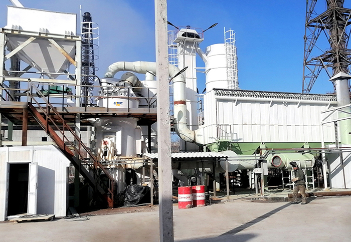
The production line of the vertical roller mill is a cost-effective and energy-efficient solution for processing powder, which is widely used in many industries, such as metallurgy, building materials, industrial solid waste treatment, thermal power plants, cement plants, and environmental protection fields. The primary purpose of this project is to finely grind raw materials through a vertical roller mill to meet the requirements of different industries for particle size, purity, and output of powder products.
Green and Intelligent Mining Machinery
Manufacturing and Export Base
Based on high quality and perfect after-sales service, our products have been
exported to more than 120 countries and regions.
Copyright © 2023 Zhengzhou Mascot Environmental Technology Co., Ltd Record number: Yu ICP No. 13021523-4





 WhatsApp
