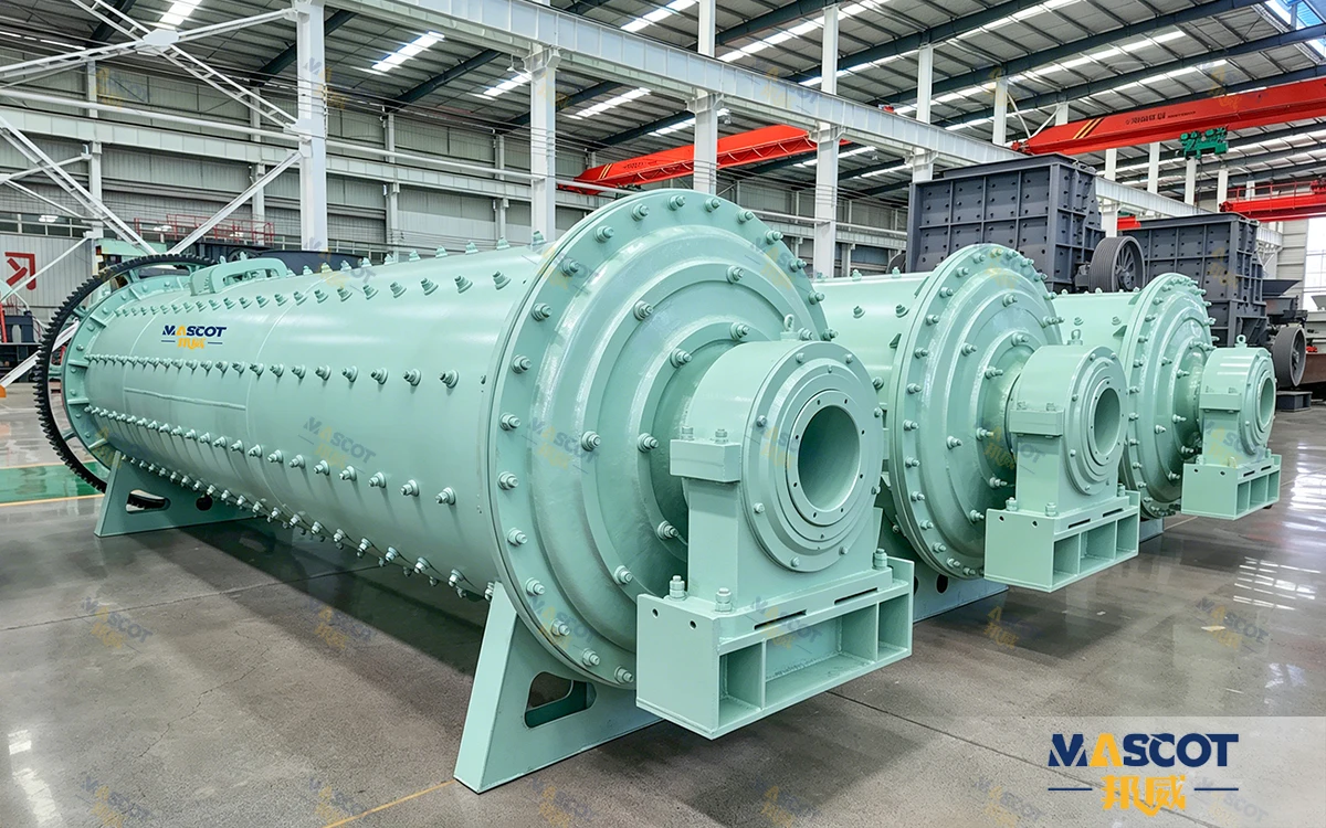
Ask a cement plant what charge its mill carries and the answer is usually a number inherited from commissioning, topped up by habit. Yet the charge is the one input the grinding team changes every shift, and it is the input that decides how many tons leave the mill per hour at the fineness the market buys. A Cement Ball Mill is a mass of steel lifted and dropped several times a minute; charge it short and it cannot break the clinker, charge it without a size mix and it grinds in one direction only, and top it up without a baseline and nobody can tell whether a falling tonnage figure came from the charge, the feed or the separator. This article sets out how the charge is built, how it is read from the mill's own instruments, and what a plant should record so that the next charging decision is a measurement rather than a guess.
Fineness and output on a cement mill are held by four things: the ball charge, the separator speed, the diaphragm setting and the feed rate. Of the four, the separator and the feed rate are adjusted continuously, the diaphragm is set at commissioning, and the charge is the one that is built once and then managed for years — which is exactly why it is the one most often left unmanaged.
The published control window is broad, and that breadth is the reason the charge matters. Output fineness on this series is adjustable from 280 to 450 m²/kg Blaine, or 1-10% residue on the 45 µm sieve, by regulating the separator speed, the ball charge and the diaphragm setting together. The same mill therefore covers ordinary Portland cement, blended cements and special cements, and the charge is the part of that capability the plant owns rather than the supplier.
The charge also sits at the centre of the plant's operating cost. In closed circuit the typical consumption is 25-32 kWh per ton of OPC at 350 m²/kg Blaine, and most of that electrical energy is spent lifting and turning the charge. A charge that is doing useful work converts that energy into tons; a charge that is worn, mismatched or oversized spends it on heat, noise and internal wear.

The charge does two jobs, in sequence. In the first chamber, large-diameter balls are lifted by the rotating shell and break the clinker by impact and abrasion, reducing a feed that arrives at up to about 25 mm. A double-layer diaphragm then retains coarse particles and lets finer material into the second chamber, where small balls finish the material to the target fineness before it is discharged through the grate to a high-efficiency separator.
Because the mill is a mechanical system, the charge mass and the drive are matched to each other. The published tables show the relationship directly: the smallest cement mill in the series carries 5 t of grinding balls behind a 55 kW drive and the largest carries 278 t behind a 3,550 kW drive. The charge is not an accessory that can be increased indefinitely; it is a mass the motor has to lift on every revolution, and the motor is specified around it.
That gives the charge a hard ceiling and a hard floor. Below the design mass, the mill cannot deliver the impact the first chamber's job requires, and tonnage falls. Above it, the drive absorbs more power for the same tons, the grinding zone runs hotter, and the extra energy leaves the mill as heat rather than as finished cement. Both conditions look similar on a daily report — output off target — and both are visible on the mill's own instruments before they show up in the laboratory.
The charge cannot fix everything, and knowing the boundary saves a week of experiments. If the finished cement is off-specification on residue while output is on target, the separator and the diaphragm setting are the first places to look. If output is on target and Blaine is unstable, the circuit's circulating load is usually responsible. The charge is the answer when tonnage falls with the fineness target unchanged — and the published guide to clinker grinding, media charging and output on this mill sets out the two-chamber arrangement that the charging procedure below works inside.

Charging starts with the published figure for the model, because that figure is the mass the mill was designed and driven around. The table below reproduces the published grinding-ball load and motor power for a representative span of the series, with a derived column that shows how the two relate.
| Model (mm) | Grinding Balls (t) | Motor Power (kW) | Installed Power per Ton of Charge (kW/t, computed) |
|---|---|---|---|
| 1200×4500 | 5 | 55 | 11.0 |
| 1500×5700 | 11 | 130 | 11.8 |
| 1830×6400 | 21 | 210 | 10.0 |
| 2200×6500 | 31 | 280 | 9.0 |
| 2400×7000 | 39 | 380 | 9.7 |
| 2400×8000 | 42 | 570 | 13.6 |
| 2600×13000 | 82 | 1000 | 12.2 |
| 3200×9000 | 95 | 1250 | 13.2 |
| 3800×12000 | 175 | 1600 | 9.1 |
| 4600×10000+3500 | 278 | 3550 | 12.8 |
How to read this table: the first three columns are the published specification for the cement ball mill series. The fourth column is a computed index — published motor power divided by the published grinding-ball load — and it is not a specification, a consumption figure or a target. It moves with gearing, drive margin and the model's position in the range, so it should be read as a single question: how much installed power sits behind each ton of steel? Across this span the answer is roughly 9 to 13 kW per ton, which is the reason a plant cannot simply load a mill with more media and expect more cement: the drive is sized to a charge, and the charge belongs to the drive.
Two consequences follow for a charging procedure. First, the published figure is the natural starting point for the first fill, and any deliberate departure from it — short-charging a mill that is running below its design tonnage, for example — should be recorded with the reason and the resulting power draw. Second, because the range spans three orders of magnitude in charge mass, a rule of thumb learned on a 1200×4500 has no meaning on a 4600×10000+3500 unit; the model's own table is the only transferable reference.
A cement mill is charged chamber by chamber, because the two chambers are asked to do different work. The first chamber carries the large-diameter balls that deliver the impact energy needed to break the clinker; the second chamber carries the smaller balls whose surface area performs the attrition that finishes the material to the target fineness. The double-layer diaphragm between them is what keeps the two size regimes apart, retaining coarse particles while letting material with sufficient fineness through.
The charging rule therefore follows from the geometry rather than from a formula: the ball sizes in the first chamber are selected against the top feed size and the clinker's grindability, and the sizes in the second chamber against the fineness the plant sells. A charge that carries the same sizes in both chambers is not a compromise between the two duties; it is a mill doing one of them and failing the other, and the failure shows up either as a first chamber that cannot absorb the feed or as a second chamber that leaves residue above specification.
Two equipment details affect how the charge behaves and belong in the same decision. The standard combination for wear life is high-chrome alloy liners with forged steel balls, which on clinker at Mohs 6-7 gives a typical liner life of 8,000-12,000 operating hours. Rubber liners are available as an option where the feed is silica-free and low noise is required, but the liner profile also shapes how the charge lifts and cascades, so a liner change is a charging decision as well as a maintenance one. Second, a three-chamber configuration with a pre-grinding compartment is available for raw meal lines, where the same machine is switched between duties. Many customers run one mill for both raw material and clinker grinding, and the charge, chamber configuration and separator settings are what is changed between them.

A charging procedure without an instrument is a maintenance ritual. The instrument is the mill itself: the power the drive draws, the tonnage the circuit delivers and the temperature the material reaches are all measured continuously on a modern cement mill, and on automated units a PLC acts on sound, power and temperature data to adjust feed rate, separator speed and water spray in real time. The table below maps each charging decision to the reading that responds to it.
| Charging Decision | What It Changes in the Mill | Where You Read It |
|---|---|---|
| Total charge mass | The mass the drive lifts and the impact energy available in the first chamber | Mill power draw against the commissioning baseline |
| Ball size mix, first chamber | Ability to break the coarsest clinker particles in the feed | Tonnage at an unchanged fineness target |
| Ball size mix, second chamber | Surface area performing the finishing attrition | Blaine and residue on the 45 µm sieve |
| Make-up quantity and interval | Whether the design size distribution still exists after months of wear | Falling tonnage while power draw holds steady |
| Diaphragm condition and setting | How the work is divided between the two chambers | Separator rejects and circulating load |
| Charge mass against cooling capacity | Heat generated in the grinding zone | Mill outlet temperature against the 110 °C limit |
The most useful of those readings is also the least used: the pair of numbers, tonnage and power draw. A worn charge loses impact capacity before it loses much mass, so the first symptom is a tonnage figure that drifts down while the power reading stays flat. A mill that is carrying more charge than its duty requires shows the opposite signature, with power elevated for the tons produced. Neither pattern is visible in a monthly output total, and both are visible within a shift if the two numbers are logged side by side at a fixed fineness — which is the same discipline the site's guide to Blaine and residue as cement fineness metrics recommends for the quality side of the mill's record.
Grinding balls are consumed continuously; the charge a plant runs in month twelve is not the charge it installed at commissioning. This is why make-up is a procedure rather than a top-up: what has to be maintained is the size distribution, not the total mass.
Track the two separately. The total ball weight tells the team how much steel is in the mill; the size distribution tells them whether that steel can still do the two jobs the chambers exist for. A charge whose mass is correct but whose distribution has collapsed into worn, undersized balls will lose impact capacity in the first chamber while the second chamber does more attrition work than it needs to, and the plant sees tonnage down and specific power up on the same ton of cement.
Three habits make the routine work. Charge on a schedule rather than in response to a bad shift, because the tonnage signal lags the wear. Record what was added, in what size, and when, so the distribution can be reconstructed instead of guessed. And re-read the power draw after each make-up: on a mill whose drive was specified around its charge, a return to the commissioning power figure at the design tonnage is the clearest available confirmation that the charge is back where it belongs.

Charging decisions have a quality consequence that shows up in the laboratory rather than on the mill's own panel. Grinding generates heat in proportion to the work being done in the grinding zone, and in a cement mill heat is a cement problem: above 110 °C the gypsum in the mix begins to dehydrate into hemihydrate, which can cause false set and reduce 28-day strength.
The countermeasure is a water-spray system at the mill inlet and outlet combined with adjustable ventilation, which keeps the material below that limit, and the gypsum input is itself a controlled figure: additions of 3-5% of clinker weight, managed against the SO3 content of the finished cement, which is normally held in the 2.5-3.5% range to ensure normal setting and strength development.
For the charging procedure, the practical link is that a mill pushed hard on charge mass in an under-cooled circuit will meet the temperature ceiling before it meets its tonnage target, and the correction that follows — less feed, more spray — will look like a mill that cannot hold output. When a mill is being deliberately charged above or below its published figure, the temperature record should be part of the same decision, and on automated units the PLC is already closing that loop on sound, power and temperature data.
A charging decision is only as good as the record it is compared against. Six entries cover it.
| Record | Why It Matters |
|---|---|
| Charge mass as loaded (t), by model | Provides the baseline against which every later power reading is judged |
| Ball size mix as loaded, per chamber | Defines the distribution that make-up has to maintain rather than approximate |
| Power draw and tonnage at a fixed fineness, over the first weeks of operation | Separates a charge problem from a feed or separator problem before habits form |
| Grade change log (OPC, PPC, PSC) with the settings used | Grade changes are made on feed proportioning, separator speed and grinding aid dosage with no mechanical change, so the settings, not the charge, are what has to be recovered |
| Liner wear and diaphragm inspection dates | Ties tonnage drift to the wear parts, and prevents a genuine liner problem being answered with more steel |
| Make-up quantity per interval (t) | Turns consumption into a rate that can be compared with the year's plan and the supplier's advice |
Two of those records connect the mill to the rest of the plant. Grade switching is a regular event in a market that moves between ordinary and blended cements, and it is done on the same machine without mechanical change; the settings used for each grade are the plant's own intellectual property. And liner inspection is the one maintenance task that lets the charging practice be audited, because liner wear patterns reflect how the charge actually behaves inside the mill rather than how it was intended to behave.
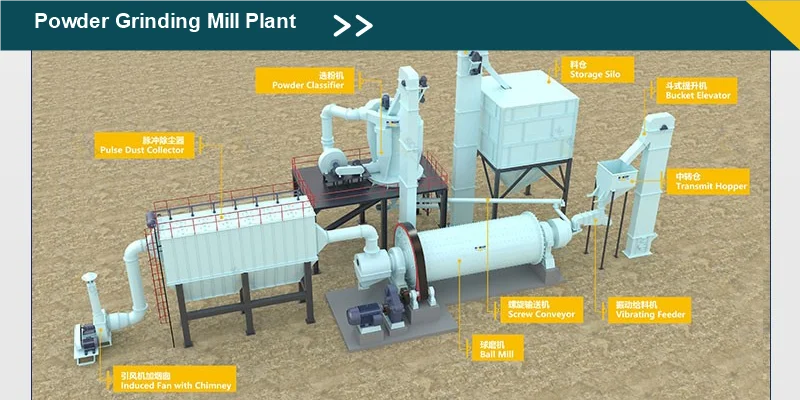
Where a complete grinding circuit is being specified rather than a single mill recharged, the comparison is easier against a documented installation. The ball mill production line reference on the site lists the full equipment set of a circuit — jaw crusher, ball mill, bucket elevator, vibrating feeder, classifier, cyclone collector, dust collector and blower — which is the list a charging strategy has to work inside, since the separator and the feed arrangement decide as much of the fineness as the charge does.
A charging practice is best judged on a mill that has been running long enough for the charge to be maintained rather than merely installed. A Bangladeshi trading group building its own cement production to serve the Dhaka construction market took imported OPC clinker at Mohs 6-7 together with natural gypsum at a feed size of 25 mm and below, and set a target of CEM I 42.5N at 340-360 m²/kg Blaine with stable early strength for ready-mix and precast customers.
The installation is a single MQG2400×7000 closed-circuit cement ball mill with a high-efficiency dynamic separator, water-spray temperature control and PLC process automation. Read against the published table, that mill carries 39 t of grinding balls behind a 380 kW drive at a cylinder speed of 20.4 r/min and a published capacity of 17-28 t/h.
The mill produces 22-25 t/h of CEM I 42.5N at 350 m²/kg with a D97 pass rate above 96%. Switching between OPC and PPC takes under two hours, which lets the plant follow demand for blended cements without a mechanical change. The customer reports that the mill reached full output within three weeks of commissioning, that the closed-circuit arrangement clearly saves power on every ton, and that cement quality is accepted by all of its ready-mix plants.

The relevant detail for a charging procedure is that the case sits inside the published envelope rather than outside it. The mill runs at the middle of its 17-28 t/h band, at a fineness inside the series' 280-450 m²/kg window, with a closed circuit separating the fineness target from the tonnage. Nothing was achieved by over-charging the mill; the output came from a chamber-correct charge inside the mass the drive was specified for.
Q1: How much grinding media should a cement ball mill carry?
A: Start from the published figure for the model — 5 t on the 1200×4500, 39 t on the 2400×7000, 278 t on the 4600×10000+3500 unit. That figure is the mass the mill and its drive were designed around. Any departure from it should be deliberate, recorded, and checked against the mill's power draw at the design tonnage.
Q2: How do I know when the charge needs topping up?
A: By watching tonnage and power draw together. A charge that has worn below its design size distribution loses impact capacity, and the first visible symptom is tonnage drifting down while the power reading stays flat. Top up on a schedule rather than after the symptom appears, and record what was added and in what size.
Q3: Does a different ball size mix change the fineness?
A: It changes which part of the job the mill does well. Large balls in the first chamber break the coarse clinker; small balls in the second provide the surface area that finishes the material. Fineness itself is set by the separator speed, the ball charge and the diaphragm setting working together, which is why fineness control is not a charge-only decision.
Q4: Can the same mill and charge produce different cement types?
A: Yes. OPC, PPC and PSC are produced on the same mill by adjusting feed proportioning, separator speed and grinding aid dosage, with no mechanical change required. On a 2400×7000 installation, switching between OPC and PPC takes under two hours.
Q5: What limits how hot the mill can run?
A: Above 110 °C the gypsum in the mix dehydrates into hemihydrate, which can cause false set and reduce 28-day strength. A water-spray system at the mill inlet and outlet combined with adjustable ventilation keeps the material below that limit, and gypsum additions are managed at 3-5% of clinker weight against an SO3 target of 2.5-3.5% in the finished cement.
Q6: What are the delivery time and warranty terms?
A: Stock items ship in 7-10 days; standard models in 15-30 days after deposit. The machine carries a 12-month warranty for the whole unit and a 12-month warranty on core components such as gearbox, liners and bearings, with 24/7 online consultation and engineers available for on-site installation, commissioning and operator training.
Charging a cement ball mill is a procedure with three parts. The first is the mass: start from the published figure for the model — from 5 t on the smallest unit to 278 t on the largest, behind drives from 55 kW to 3,550 kW — because the charge and the drive are matched to each other. The second is the distribution: large balls in the first chamber to break the clinker, small balls in the second to finish it, held apart by the double-layer diaphragm, and maintained by make-up that restores a size mix rather than merely adding weight. The third is the readout: power draw against tonnage at a fixed fineness, checked against the commissioning baseline and against the 110 °C temperature limit that protects the gypsum and the cement's 28-day strength.
Held on those three, a closed-circuit installation of the type described in the Dhaka case — 39 t of balls, a 380 kW drive, 22-25 t/h of CEM I 42.5N at 350 m²/kg with a D97 pass rate above 96% — runs where it was designed to run, and the charge stays a managed input rather than an inherited number. The Cement Ball Mill series covers 1.6-210 t/h with a published Blaine window of 280-450 m²/kg, and where cement and slag are being ground in the same plant, the comparison between mill types is set out in vertical roller mill or ball mill for cement and slag. Send your clinker data, target Blaine and required tonnage, and the mill, the charge and the circuit can be specified against your numbers rather than a catalogue range.

About of Mascot
Zhengzhou Mascot Industry is a high-tech mining equipment company integrating R&D, manufacturing, sales, and after-sales service. Focusing on crushing, grinding, and mineral processing equipment, we provide professional solutions to our customers. We are ISO9001:2015 certified, and our products include mobile crushing plants, crawler crushing plant, construction waste crushing plants, jaw crushers, sand making machines, cone crushers, fine crushers, grinding mills, ball mills, etc., all with reliable performance to meet diverse project needs.
• Professional pre-sales support: Free project design and comprehensive solutions to help you accurately select the right equipment;
• Comprehensive on-site service: Providing installation guidance and worker training to ensure smooth equipment commissioning;
• Reliable after-sales guarantee: A complete after-sales system, timely response to technical inquiries and equipment maintenance, ensuring long-term stable operation.
To protect your rights, please contact us through the following official channels for professional service:
WhatsApp: 0086-16650273865
Email: mascot@mascotenv.com
We are committed to providing high-quality equipment and full-cycle services to deliver comprehensive intelligent solutions for the global mining industry!

The Raymond mill production line is a highly efficient system designed for grinding operations, with a focus on energy efficiency, durability, and productivity. It caters to the needs of users by offering fine powder products in non-metallic ores, coal powder, and slag processing, aiding enterprises in achieving sustainable growth.

This production line utilizes a three-ring medium-speed micro-grinding mill as the central equipment, complemented by other auxiliary equipment like hammer crushers, bucket elevators, and storage silos to establish a comprehensive grinding operation system. It has demonstrated strong potential for application and market competitiveness in industries such as construction, chemical industry, and new materials.

The high-pressure grinding mill production line is a project specially designed for efficient grinding operations. It is widely used in metallurgy, building materials, the chemical industry, highways, water conservancy hydropower, and other industries. It is a suspended roller mill that uses springs to increase pressure. It can achieve efficient grinding processing of various non-metallic raw materials. It has high efficiency, stability, and environmental protection characteristics.

YGMX Enhanced High-Pressure Mill is a new type of high-performance grinding equipment, and the biggest improvement of this milling equipment lies in the increase of the high-pressure spring system in the grinding roller part. Compared with the traditional high-pressure roller mill, it has a wider scope of application and excellent performance to meet the production needs of a variety of powder fineness. It is widely used in non-metallic minerals, chemicals, building materials, metallurgy, environmental protection, etc. Multiple areas.

The gypsum grinding production line is an efficient, stable, and environmentally friendly production solution, which is widely used in construction, decoration, the chemical industry, and other fields. In addition, the grinding process is particularly critical, which directly affects the quality and particle size of the final product. With the continuous development of science and technology, the technical level and production efficiency of gypsum grinding production lines will be further improved, providing strong support for the development of the gypsum processing industry.
Green and Intelligent Mining Machinery
Manufacturing and Export Base
Based on high quality and perfect after-sales service, our products have been
exported to more than 120 countries and regions.
Copyright © 2023 Zhengzhou Mascot Environmental Technology Co., Ltd Record number: Yu ICP No. 13021523-4





 WhatsApp